NDR: Virtual Sensor Deployment (Hyper-V)
Description
 CAUTION: The examples below are intended to be serve as general guidelines. Your platform or software version may differ, resulting in variations in images, screens, options, or other elements.
- This guide is intended to serve as an example only. Users must modify applicable details, such as IP addresses, subnets, and device names, to align with their specific environment.
- Exercise caution when making changes to your firewall or environment, as unplanned modifications can result in downtime, depending on the complexity of the configuration and infrastructure.
- Your experience may vary if you are using a different software version or a product from another brand or manufacturer. Please note that you are solely responsible for the configuration and management of your devices.
Site Preparation
This process requires a Microsoft Hyper-V environment on a Windows server. Windows Server 2016 is the tested version.
You will need:
- Server switch with a physical network interface that supports promiscuous mode
- One IP address with access to a default gateway
- A Stellar Cyber license that can be applied to the sensor
- Open firewall ports for log ingestion
- Open firewall ports for Network Traffic, Sandbox, and IDS features, as necessary
Downloading Images
You can download the images for modular sensors using the link below.
- Download the modular sensor image from the following URL: aella-modular-ds-5.4.0.vhdx
- Our example assumes that the file has been downloaded into the local C:\Users\Public\Documents\Hyper-V\Virtual hard disks\ folder.
1. Creating a New VM
- In your Hyper-V manager and select Action | New | Virtual Machine.
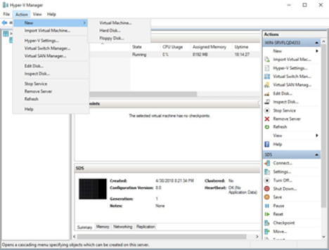
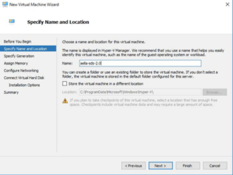
- Specify a name for the new security sensor. This can be any legal VM name but it is recommended to adopt a site convention so that the name identifies the type of sensor. The screen will look similar to the following image.
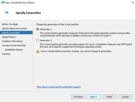
- Enter the Generation parameter. The guest Operating System is a 64-bit OS so "Generation 1" is a good choice as shown in the following image.
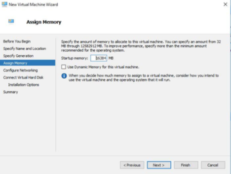
- Next, assign memory according to the sensor's expected workload, as stated in Virtual Appliance Sizing Specifications.
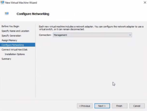
- Configure the Management network interface. You can either enter a static IP or configure using a DHCP server. This is the interface that will be used for the sensor to send its Interflow data records to the data processor. The networking is selected as in the following image.
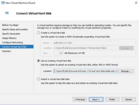
- Connect the Virtual Disk image that was downloaded in the site preparation mentioned above. In the dialog box use the Use existing option as shown in the following image. If the image was placed in a different location adjust the Location field appropriately.
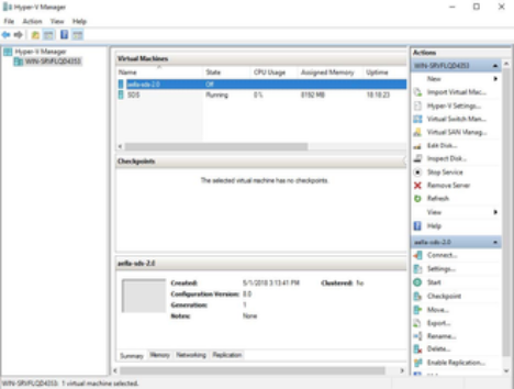
- At this point the creation of the VM is complete and it should appear in the Hyper-V Manager screen in a manner similar to the following image.
Changing the Processor Setting
Before activating the VM, it needs to have the proper number of CPU cores allocated to it. Select the VM in the list and click Settings | Processor menu options. In the resulting dialog box, change the number of processors according to the sensor's expected workload, as stated in Virtual Appliance Sizing Specifications.

Enabling SSSE3 and Disabling Processor Compatibility Mode
The sensor VM must have SSSE3 enabled and processor compatibility mode disabled in order for the Modular Sensor to operate correctly.
In most cases, SSSE3 will already be enabled. However, if you encounter issues with packet collection or Interflow data generation, you can use the instructions below to ensure that SSSE3 is enabled.
Ensure that Processor Compatibility Mode is Disabled
Stellar Cyber sensors deployed in Hyper-V must have the processor compatibility feature disabled to ensure that the SSSE3 instruction set can be used and that aella_flow runs properly. Although the sensor VM starts and appears to run correctly with processor compatibility enabled, stability issues will eventually occur due to high CPU usage.
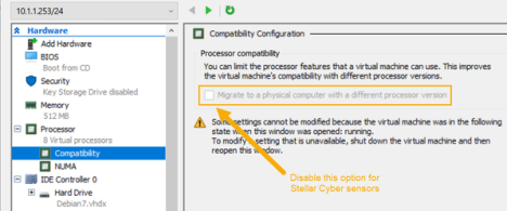
You can verify that processor compatibility mode is disabled in the same dialog box where you just assigned CPU cores:
- Expand the Processor entry in the left pane of the Settings dialog box.
- Click on the Compatibility entry.
- Ensure that Migrate to a physical computer with a different processor is disabled and click OK.
The image below shows you the option that must be disabled for Stellar Cyber sensors:
Adding an Interface
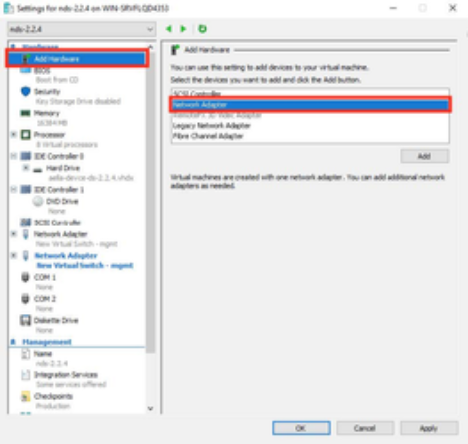
- The sensor requires a connection to the virtual switch. Click Add Hardware | Network Adapter as shown in the following image. Note that you can only add a network adapter to the VM while it is powered off.
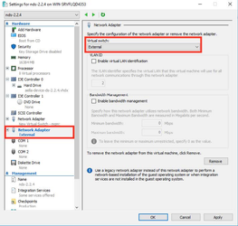
- After the interface is created, select your applicable virtual switch.
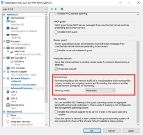
- Expand the associated network adapter and click Advanced Features. Set the mirroring mode of the aggregator to Destination. This is shown in the following image.
- When you have finished adding the interface, power the VM on.
3. Connecting the Sensor to the Stellar Cyber Platform
To connect the sensor to the Stellar Cyber Platform:
- Log in to your new sensor. The default username/password is aella/changeme. You are immediately prompted to change the password.
- Change the password.
- After you change the password, your session closes automatically. When you log back in with your new credentials, the prompt changes to DataSensor>.
- Set the host name. The host name is displayed in Stellar Cyber and should be unique for each sensor:
- set hostname <new hostname>
- Set IP parameters for the management port. The commands are as follows (Substitute your own IP parameters for those shown in bold).
- set interface management ip 192.168.14.100/255.255.255.0
- set interface management gateway 192.168.14.1
- set interface management dns 8.8.8.8
- Verify the IP settings with the show interface command.
- Assign the tenant
- The Tenant ID was provided in the ticket.
- set tenant_id <Tenant ID from Stellar Cyber>
- Use the set cm command to specify the hostname to reach the management interface of the Data Processor.
- When specifying a hostname, the system attempts to verify the hostname with the DNS server. If the DNS server is not reachable, the system reports the error and lets you either proceed with the configured hostname or quit.
- <Applicable CM URL from below>
- NOAM Console: cm-solutionsgrantedinc.stellarcyber.cloud
- EMEA Console: cm-emea-snwl.stellarcyber.cloud
- Verify with the show cm command. You should see the IP address of the DP listed as the CM Controller and the Status should be Established.
- Log out with the quit command.
4. Sensor Authorization
Once complete, please reply to your engineer’s email with the following information so we can confirm that we are seeing the sensor and authorize it.
Sensor Details
- Sensor Hostname
- Sensor IP Address
