How can I configure a Site to Site VPN with multiple network overlaps (NAT over VPN)?
Description
This article will guide you through the process of configuring the SonicWall to translate multiple networks for use across a Site to Site VPN.
 NOTE: Due to the way this is processed, the same application can be completed for a Tunnel Interface (Route Based VPN).
Below is a diagram that will be used as an example case throughout this article as a guide to help establish the concept.
 EXAMPLE: As seen in the example, the two sites share the internal networks of 192.168.168.0/24 and 192.168.1.0/24. As a result they will be translated on both ends to ensure there are no overlaps of networks coming across the tunnel. Doing so, we will be establishing the VPN by negotiating the tunnel with the 10.168.168.0/24, 10.168.1.0/24, 10.168.169.0/24, and 10.168.2.0/24 networks.

 TIP: If you are trying to setup a Site to Site VPN with a single network translation, the SonicWall has a built in feature for this. See How to Configure NAT over VPN in a Site to Site VPN for more information on how to configure this.
Resolution
NOTE: The SIte A configuration here is based on firmware SonicOS 6.2 and Below and SIte B configuration is based on firmware SonicOS 6.5 and Later.Based on what firmware you are on, please configure accordingly.
Site A Configuration
- Log in to the SonicWall with your admin account.
- Navigate to Network | Address Objects.
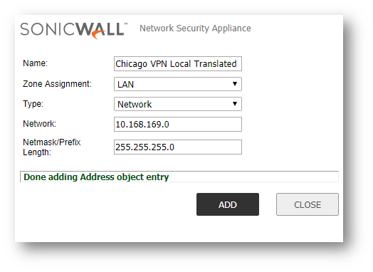
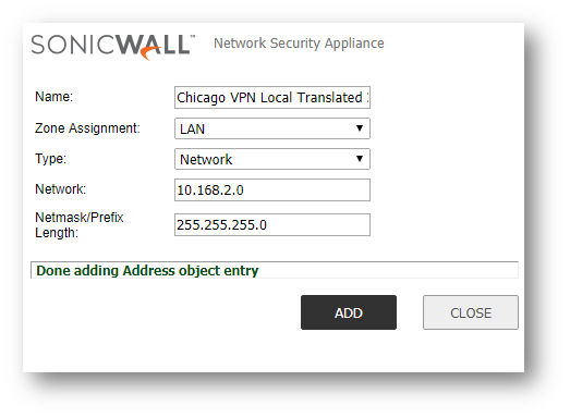
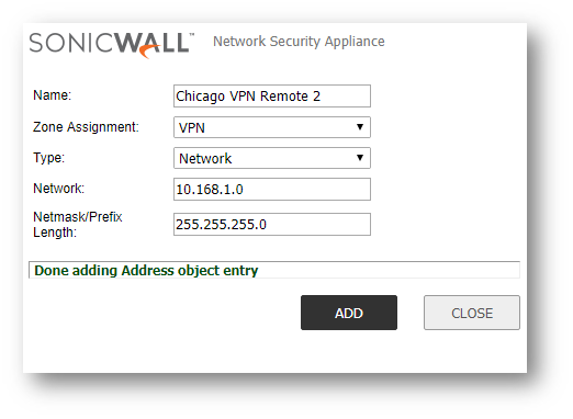
- Click Add at the bottom of the screen and create the address objects for the Local site networks (if they do not exist), the translations of the local site networks, and the translations of the remote site's networks. You should have a minimum of 6 address objects (more if you are translating for more than 2 network overlaps). EXAMPLE: In the Example below, we are configuring the SonicWall Appliance as though we are at Site A (Chicago).


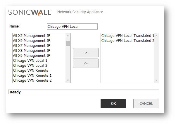
- Access the Address Groups tab and click Add... at the bottom of the screen to create new groups for the Translated Local Networks and the Translated Remote Networks.

- Navigate to Network | NAT Policies.
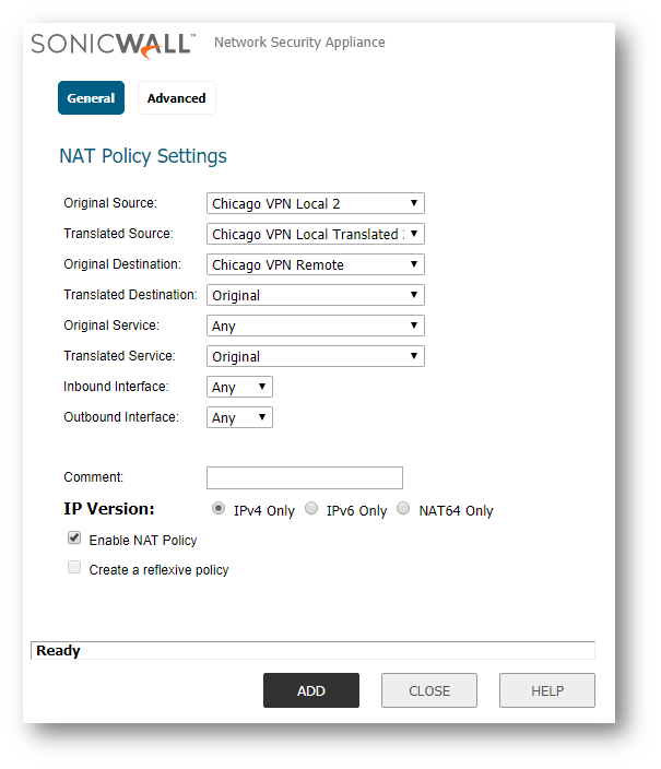
- Click Add at the bottom of the page to create new NAT policies for each of the local networks needing to be translated.
NOTE: While our example only has two networks being translated, your network may require more NAT Policies than what we display below.The format for the NAT policies will be as follows:
Outbound NAT policy
Original Source: Local Network
Translated Source: Local Network Translation
Original Destination: Remote Network Translation (Group)
Translated Destination: Original
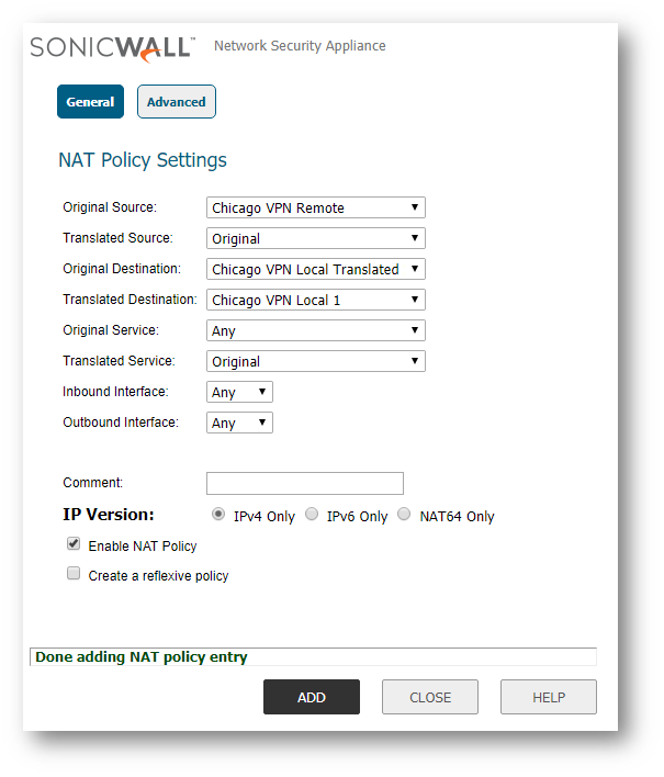
Inbound NAT policy
Original Source: Remote Network Translation (Group)
Translated Source: Original
Original Destination: Local Network Translation
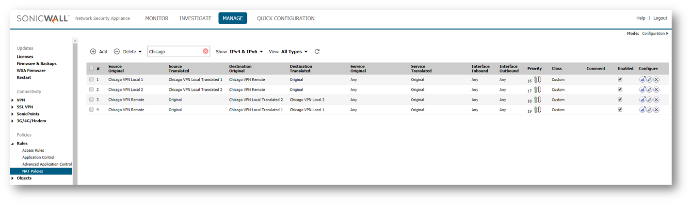
Translated Destination: Local Network EXAMPLE: Screenshots included below for our examples of the 2 Inbound and 2 Outbound NAT policies needed for the case study.


- Navigate to VPN | Settings.
- Click Add to create your new VPN.
- On the General tab, fill-in the Name, IPSec Primary Gateway Name or Address and Shared Secret fields.

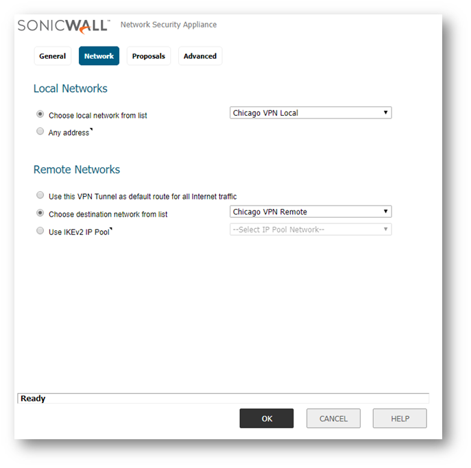
- On the Network Tab, select the Local Translated Address Group in the Choose local network from list field and select the Remote Translated Address Group in the Choose destination network from list field.
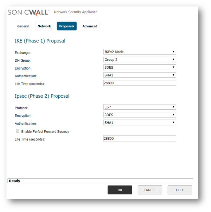
- On the Proposals tab, select the preferred settings for Exchange, DH Group, Encryption, Authentication, Life Time (seconds), Protocol, and Enable Perfect Forward Secrecy.

- Make the appropriate adjustments on the Advanced tab as necessary. NOTE: Ensure at least one side of the VPN has keepalive enabled to keep the tunnel active.

- Click OK .
- Confirm that the VPN is active by seeing a green circle appear next to each of the network destinations on the VPN | Settings page. NOTE: You may need to refresh the page for the settings to take effect. This can also be tested with a ping from local to remote or remote to local.

Site B Configuration
- Log in to the SonicWall with your admin account.
- Click Manage in the top navigation menu.
- Navigate to Objects | Address Objects.
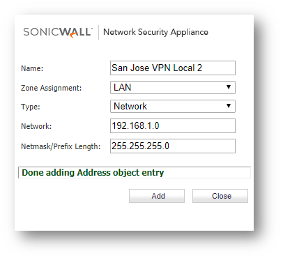
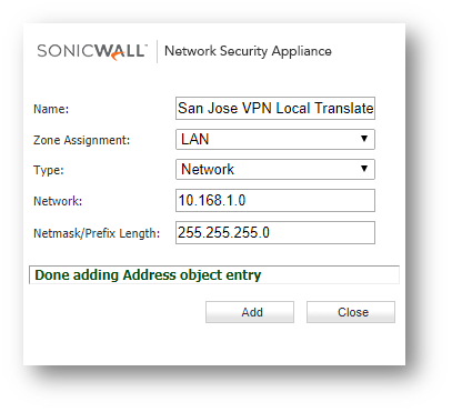
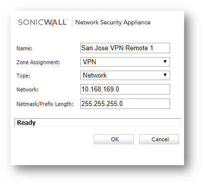
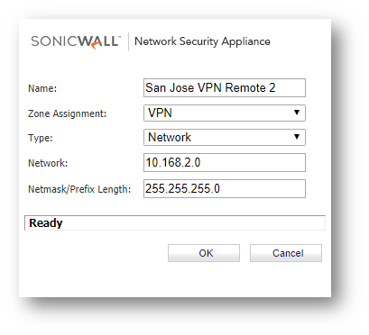
- Click Add at the top of the screen and create the Address Objects for the Local site networks (if they do not exist), the translations of the local site networks, and the translations of the remote site's networks. You should have a minimum of 6 address objects (more if you are translating for more than 2 network overlaps). EXAMPLE: In the Example below, we are configuring the SonicWall Appliance as though we are at Site B (San Jose).


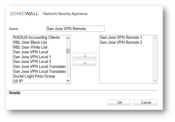
- Access the Address Groups Tab and click Add at the top of the screen to create new groups for the Translated Local Networks and the Translated Remote Networks.

- Navigate to Rules | NAT Policies.
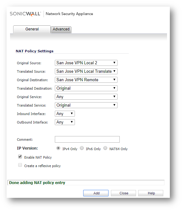
- Click Add at the bottom of the page to create new NAT policies for each of the local networks needing to be translated.
NOTE: While our example only has two networks being translated, your network may require more NAT Policies than what we display below.The format for the NAT policies will be as follows:
Outbound NAT policy
Original Source: Local Network
Translated Source: Local Network Translation
Original Destination: Remote Network Translation (Group)
Translated Destination: Original
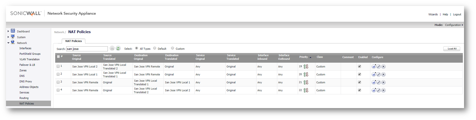
Inbound NAT policy
Original Source: Remote Network Translation (Group)
Translated Source: Original
Original Destination: Local Network Translation
Translated Destination: Local Network EXAMPLE: Screenshots included below for our examples of the 2 Inbound and 2 Outbound NAT policies needed for the case study.

- Navigate to VPN | Base Settings.
- Click ADD to create your new VPN
- On the General tab, fill-in the Name, IPSec Primary Gateway Name or Address and Shared Secret fields.

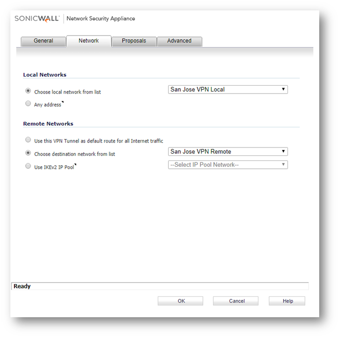
- On the Network Tab, select the Local Translated Address Group in the Choose local network from list field and select the Remote Translated Address Group in the Choose destination network from list field.
- On the Proposals tab, select the preferred settings for Exchange, DH Group, Encryption, Authentication, Life Time (seconds), Protocol, and Enable Perfect Forward Secrecy.
- Make the appropriate adjustments on the Advanced tab as necessary. NOTE: Ensure at least one side of the VPN has keepalive enabled to keep the tunnel active.

- Click OK.
- Confirm that the VPN is active by seeing a green circle appear next to each of the network destinations on the VPN | Settings page. NOTE: You may need to refresh the page for the settings to take effect. This can also be tested with a ping from local to remote or remote to local.

