How can I configure a main mode VPN between a SonicWall and Palo Alto firewall?
Description
When configuring a Site-to-Site VPN tunnel in SonicOS Enhanced firmware using Main Mode with the SonicWall appliances (Site A) and Palo Alto firewall (Site B) must have routable Static WAN IP address.
Network Setup

Deployment Steps
- Creating Address Objects for VPN subnets.
- Configuring a VPN policy on Site A SonicWall.
- Configuring a VPN policy on Site B Palo Alto firewall.
- How to test this scenario.
Resolution for SonicOS 6.5
This release includes significant user interface changes and many new features that are different from the SonicOS 6.2 and earlier firmware. The below resolution is for customers using SonicOS 6.5 firmware.
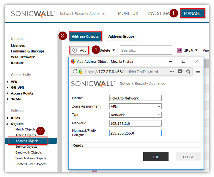
Creating Address Objects for VPN subnets
- Login to the SonicWall management Interface.
- Click Manage in the top navigation menu.
- Navigate to Objects | Address Objects.
- Click Address objects Tab.
- Click Add Configure the Address Objects as mentioned in the figure above, click Add and click close when finished.
Configuring a VPN policy on Site A SonicWall
- Click Manage in the top navigation menu.
- Navigate to VPN | Base Settings page.
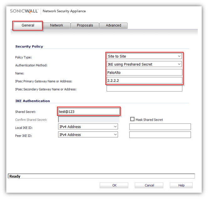
- Click Add. The VPN Policy window is displayed.
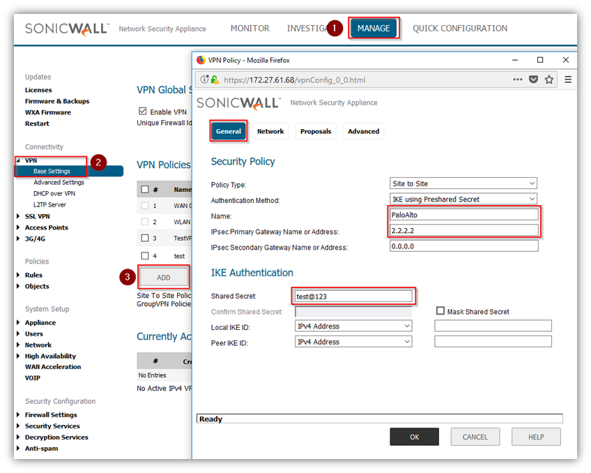
- Click General tab.
- Select IKE using Preshared Secret from the Authentication Method menu.
- Enter a name for the policy in the Name field.
- Enter the WAN IP address of the remote connection in the IPSec Primary Gateway Name or Address field (Enter Site B's Palo Alto WAN IP address).
- If the Remote VPN device supports more than one endpoint, you may optionally enter a second host name or IP address of the remote connection in the IPSec Secondary Gateway Name or Address field.
 NOTE: Secondary gateways are not supported with IKEv2.
 - Enter a Shared Secret password to be used to setup the Security Association the Shared Secret and Confirm Shared Secret fields. The Shared Secret must be at least 4 characters long, and should comprise both numbers and letters.
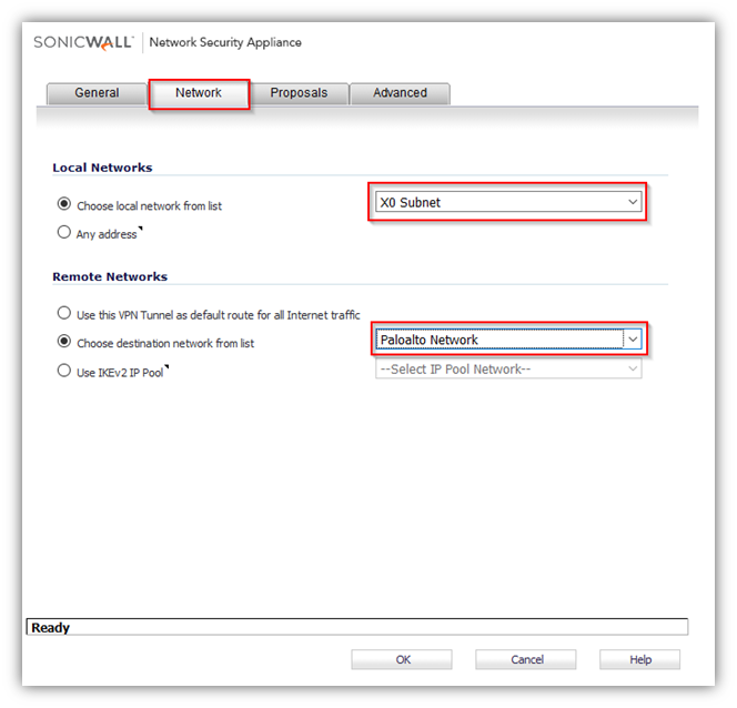
- Click Network tab.
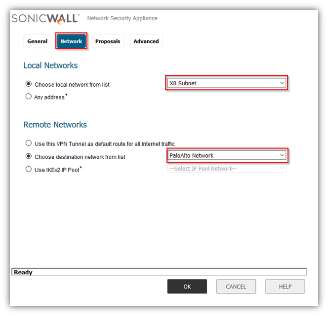
- Under Local Networks, select a local network from Choose local network from list: and select the address object X0 Subnet (LAN Primary Subnet).
- Under Destination Networks, select Choose destination network from list: and select the address object Remote network (Site B network).
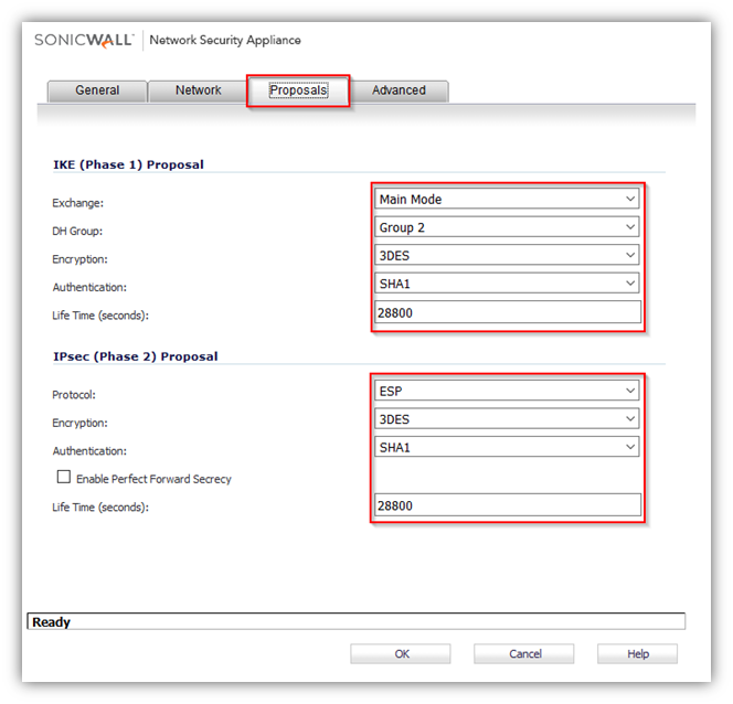
- Click Proposals tab.

- Under IKE (Phase 1) Proposal, select Main Mode from the Exchange menu. Aggressive Mode is generally used when WAN addressing is dynamically assigned. IKEv2 causes all the negotiation to happen via IKE v2 protocols, rather than using IKE Phase 1 and Phase 2. If you use IKE v2, both ends of the VPN tunnel must use IKE v2.
- Under IKE (Phase 1) Proposal, the default values for DH Group, Encryption, Authentication, and Life Time are acceptable for most VPN configurations. Be sure the Phase 1 values on the opposite side of the tunnel are configured to match. You can also choose AES-128, AES-192, or AES-256 from the Authentication menu instead of 3DES for enhanced authentication security.
NOTE:The Windows 2000 L2TP client and Windows XP L2TP client can only work with DH Group 2. They are incompatible with DH Groups 1 and 5. - Under IPSec (Phase 2) Proposal, the default values for Protocol, Encryption, Authentication, Enable Perfect Forward Secrecy, DH Group, and Lifetime are acceptable for most VPN SA configurations. Be sure the Phase 2 values on the opposite side of the tunnel are configured to match.
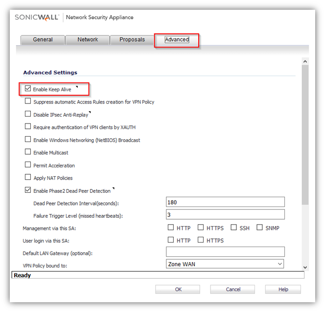
- Click Advanced tab.
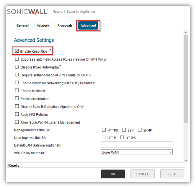
- Select Enable Keep Alive to use heartbeat messages between peers on this VPN tunnel. If one end of the tunnel fails, using Keepalives will allow for the automatic.
- Renegotiation of the tunnel once both sides become available again without having to wait for the proposed Life Time to expire.
- Select Enable Windows Networking (NetBIOS) Broadcast to allow access to remote network resources by browsing the Windows® Network Neighborhood.
- To manage the local SonicWall through the VPN tunnel, select HTTP, HTTPS, or both from Management via this SA. Select HTTP, HTTPS, or both in the User login via this SA to allow users to login using the SA.
- If you wish to use a router on the LAN for traffic entering this tunnel destined for an unknown subnet, for example, if you configured the other side to Use this VPN Tunnel as default route for all Internet traffic, you should enter the IP address of your router into the Default LAN Gateway (optional) field.
- Select an interface or zone from the VPN Policy bound to menu. A Zone WAN is the preferred selection if you are using WAN Load Balancing and you wish to allow the VPN to use either WAN interface.
- Click OK .
Configuring a VPN policy on Site B Palo Alto Firewall
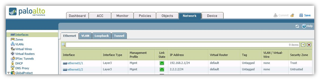
- Palo Alto Interfaces with LAN and WAN.
Creating IKE Crypto profile and IPSec Crypto profiles
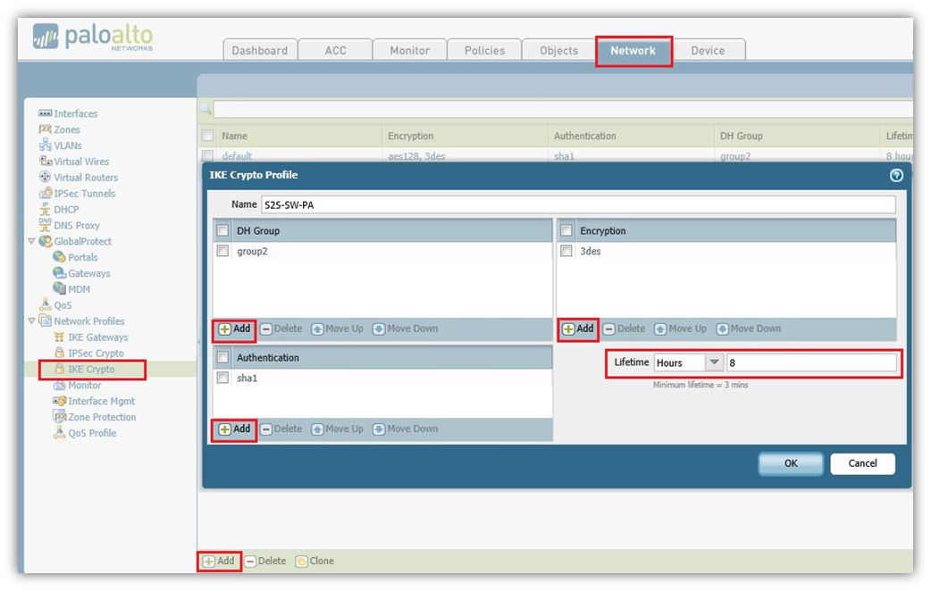
- Navigate to Network tab, Click IKE Crypto Add New Crypto Profile.
- Here we named as S2S-SW-PA and added DH-group as Group2, Authentication added sha1 and Encryption added 3des, Lifetime Selected as 8 hours. Click on OK to save the Profile.
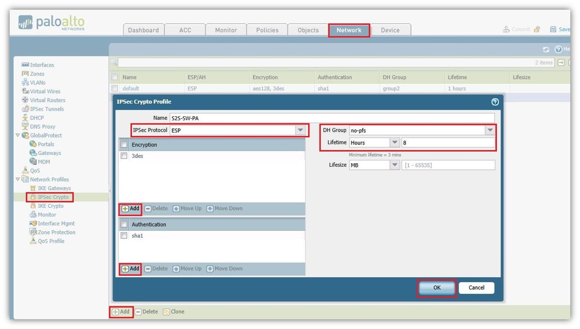
- Navigate to Network tab, click IPSec Crypto Add New Profile.
- Here we named as S2S-SW-PA. Selected IPSec Protocol as ESP, Encryption added 3des, Authentication added sha1 and DH Group Selected as no-pfs, Lifetime Selected as 8 hours. Click OK .
Configuring IKE Gateway with the pre-shared key and the corresponding IKE Crypto Profile. The “Identification” fields are not needed
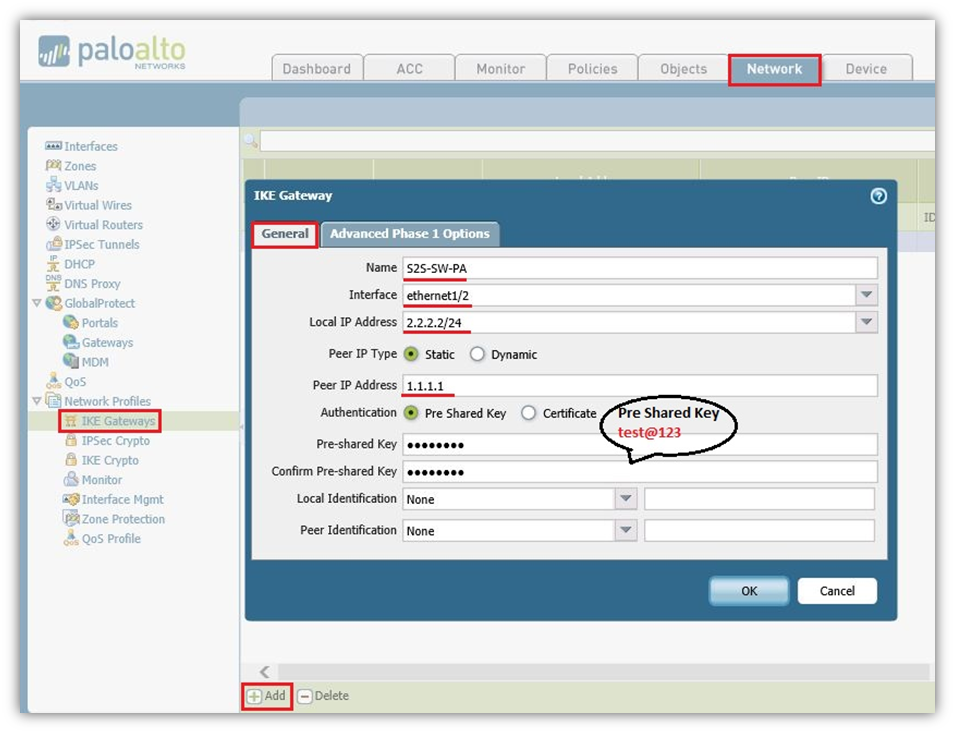
- On the Network tab, Click IKE Gateway Add IKE Gateway.
- In the General Tab we again named as S2S-SW-PA (Could be any name).
- Selected Interface Ethernet1/2 which is WAN.
- Local IP Address is WAN IP address of the Palo Alto which is 2.2.2.2/24.
- Peer IP Type Static as per SonicWall hence selected Static and SonicWall WAN IP is 1.1.1.1.
- Authentication Type Selected as Pre Shared Key and It should be same as SonicWall which is test@123.
Advanced Phase 1 Option Tab
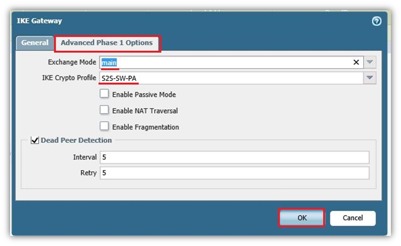
- Exchange Mode Select Main Mode.
- IKE Crypto Profile Select the Profile which we had already created S2S-SW-PA.
- Click OK.
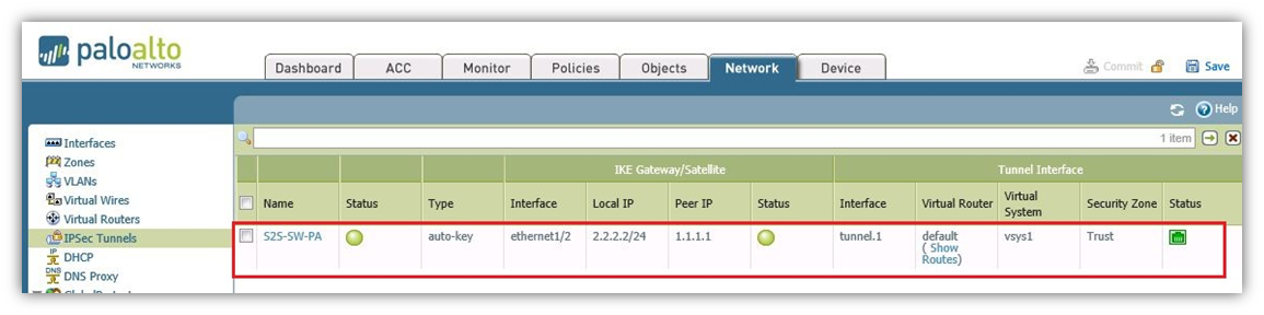
Create Tunnel Interface within a virtual router (e.g., “default”) and a security zone
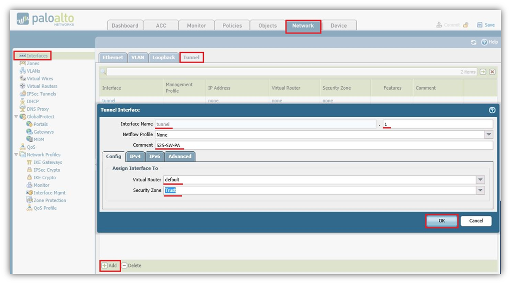
- Navigate to Network Tab, Click Interfaces and on Tunnel Tab Add New tunnel Interface.
- In Tunnel Interface type a number just for identification of the tunnel. Here in this case we selected 1.
- On Config Tab, Select Virtual Router as Default and Security Zone Select Trust.
- The interface does not need an IP address. Click OK .
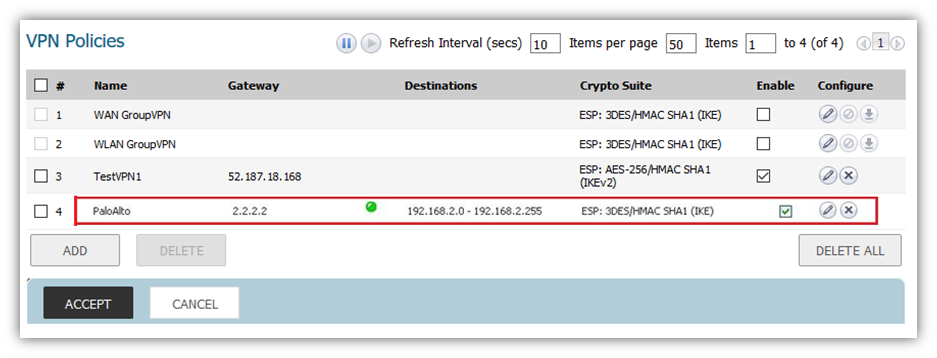
IPSec Tunnel: Trying all together: tunnel interface, IKE gateway, IPSec crypto profile. Furthermore, the Proxy IDs (= protected networks) are set here
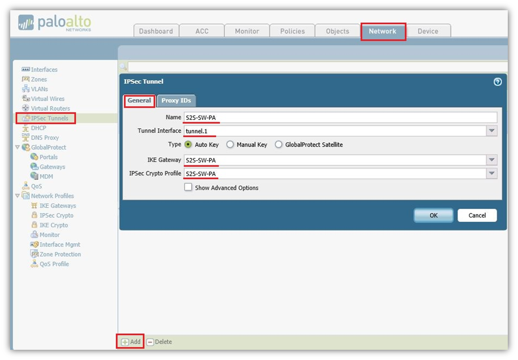
- Navigate to Network IPSec Tunnel, Add new IPSec Tunnel.
- In General tab Name S2S-SW-PA (Could Choose any Name).
- Tunnel Interface Select tunnel.1 which we had created on Tunnel interface.
- Type Select-Auto Key (Default).
- IKE Gateway Select S2S-SW-PA which we had created on IKE Gateway.
- IPSec Crypto Profile Select S2S-SW-PA which had created on IPSec Crypto Profile.
Proxy IP Tab
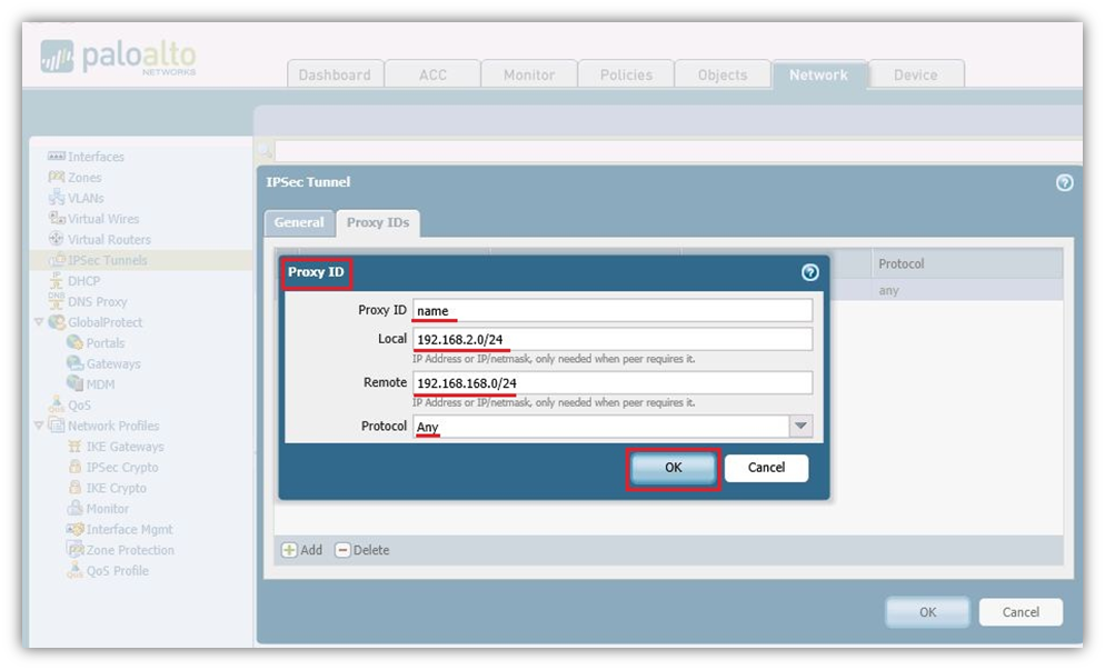
- Proxy ID Name: Choose any name.
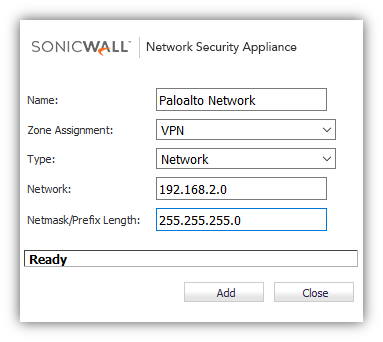
- Local: 192.168.2.0/24 Select the local LAN subnet of Palo Alto.
- Remote: 192.168.168.0/24 Select the remote LAN subnet of SonicWall.
- Protocol: Any.
- Click OK .
Static route to the destination network through the tunnel interface (without next hop address)
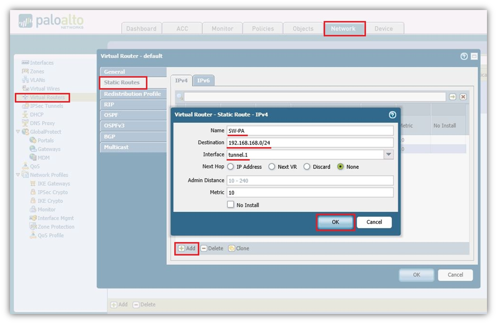
- Navigate to Network, Virtual Routers on the default policy add a static route.
- Name: Choose the name, in our case we have SW-PA.
- Destination: 192.168.168.0/24 Subnet of SonicWall LAN.
- Interface: Select the tunnel.1 Interface.
- Next Hop: None.
- Metric: 10 by default.
- Click OK .
Policies from trust zones to the zone in which the tunnel interface resides.

- Navigate to Policies and under Security add a new policy.
- Allow Trusted Local Address 192.168.2.0/24 to 192.168.168.0/24 Remote Subnet for any application and for any Services.
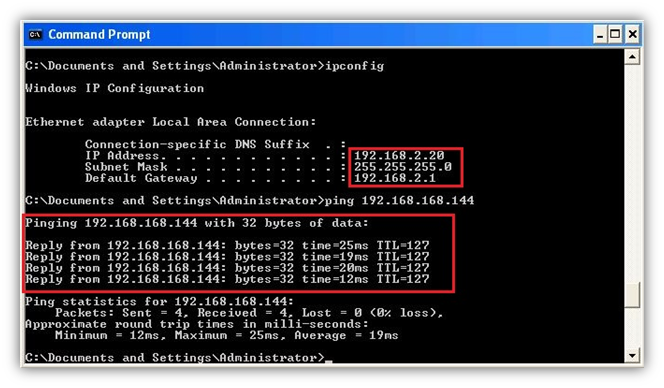
How to Test this Scenario
- Check the tunnel is UP on both the devices and try to ping addresses from Site A to Site B or Vice Versa.
- Tunnel is UP on SonicWall.
- Windows XP PC behind SonicWall which is 192.168.168.144 able to ping Windows XP PC which is behind Palo Alto 192.168.2.20.
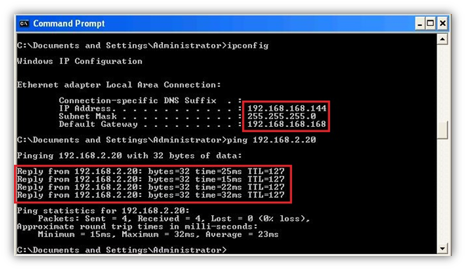
- Tunnel is UP on Palo Alto.
- Windows XP PC behind Palo Alto which is 192.168.2.20 able to ping Windows XP PC which is behind SonicWall 192.168.168.144.
Resolution for SonicOS 6.2 and Below
The below resolution is for customers using SonicOS 6.2 and earlier firmware. For firewalls that are generation 6 and newer we suggest to upgrade to the latest general release of SonicOS 6.5 firmware.
Creating Address Objects for VPN subnets
- Login to the SonicWall management Interface
- Navigate to Network | Address Objects, scroll down to the bottom of the page and click ADD.
- Configure the Address Objects as mentioned in the figure above, click Add and click close when finished.
Configuring a VPN policy on Site A SonicWall
- Navigate to VPN | Settings page and Click Add. The VPN Policy window is displayed.
- Click General tab.
- Select IKE using Preshared Secret from the Authentication Method menu.
- Enter a name for the policy in the Name field.
- Enter the WAN IP address of the remote connection in the IPSec Primary Gateway Name or Address field (Enter Site B's Palo Alto WAN IP address).
- If the Remote VPN device supports more than one endpoint, you may optionally enter a second host name or IP address of the remote connection in the IPSec Secondary Gateway Name or Address field.
NOTE: Secondary gateways are not supported with IKEv2. - Enter a Shared Secret password to be used to setup the Security Association the Shared Secret and Confirm Shared Secret fields. The Shared Secret must be at least 4 characters long, and should comprise both numbers and letters.
- Click Network.
- Under Local Networks, select a local network from Choose local network from list: and select the address object X0 Subnet (LAN Primary Subnet).
- Under Destination Networks, select Choose destination network from list: and select the address object Remote network (Site B network).
- Click Proposals tab.
- Under IKE (Phase 1) Proposal, select Main Mode from the Exchange menu. Aggressive Mode is generally used when WAN addressing is dynamically assigned. IKEv2 causes all the negotiation to happen via IKE v2 protocols, rather than using IKE Phase 1 and Phase 2. If you use IKE v2, both ends of the VPN tunnel must use IKE v2.
- Under IKE (Phase 1) Proposal, the default values for DH Group, Encryption, Authentication, and Life Time are acceptable for most VPN configurations. Be sure the Phase 1 values on the opposite side of the tunnel are configured to match. You can also choose AES-128, AES-192, or AES-256 from the Authentication menu instead of 3DES for enhanced authentication security.
NOTE:The Windows 2000 L2TP client and Windows XP L2TP client can only work with DH Group 2. They are incompatible with DH Groups 1 and 5. - Under IPSec (Phase 2) Proposal, the default values for Protocol, Encryption, Authentication, Enable Perfect Forward Secrecy, DH Group, and Lifetime are acceptable for most VPN SA configurations. Be sure the Phase 2 values on the opposite side of the tunnel are configured to match.
- Click Advanced tab.
- Select Enable Keep Alive to use heartbeat messages between peers on this VPN tunnel. If one end of the tunnel fails, using Keepalives will allow for the automatic.
- Renegotiation of the tunnel once both sides become available again without having to wait for the proposed Life Time to expire.
- Select Enable Windows Networking (NetBIOS) Broadcast to allow access to remote network resources by browsing the Windows® Network Neighborhood.
- To manage the local SonicWall through the VPN tunnel, select HTTP, HTTPS, or both from Management via this SA. Select HTTP, HTTPS, or both in the User login via this SA to allow users to login using the SA.
- If you wish to use a router on the LAN for traffic entering this tunnel destined for an unknown subnet, for example, if you configured the other side to Use this VPN Tunnel as default route for all Internet traffic, you should enter the IP address of your router into the Default LAN Gateway (optional) field.
- Select an interface or zone from the VPN Policy bound to menu. A Zone WAN is the preferred selection if you are using WAN Load Balancing and you wish to allow the VPN to use either WAN interface.
- Click OK .
Configuring a VPN policy on Site B Palo Alto Firewall
- Palo Alto Interfaces with LAN and WAN
Creating IKE Crypto profile and IPSec Crypto profiles
- Navigate to Network Tab, click IKE Crypto Add New Crypto Profile.
- Here we named as S2S-SW-PA and added DH-group as Group2, Authentication added sha1 and Encryption added 3des, Lifetime Selected as 8 hours. Click OK .
- Navigate to Network tab, click IPSec Crypto Add New Profile.
- Here we named as S2S-SW-PA. Selected IPSec Protocol as ESP, Encryption added 3des, Authentication added sha1 and DH Group Selected as no-pfs, Lifetime Selected as 8 hours. Click on OK to save the Profile.
Configuring IKE Gateway with the pre-shared key and the corresponding IKE Crypto Profile. The “Identification” fields are not needed
- On the Network tab, click IKE Gateway Add IKE Gateway.
- In the General Tab we again named as S2S-SW-PA (Could be any name).
- Selected Interface Ethernet1/2 which is WAN.
- Local IP Address is WAN IP address of the Palo Alto which is 2.2.2.2/24.
- Peer IP Type Static as per SonicWall hence selected Static and SonicWall WAN IP is 1.1.1.1.
- Authentication Type Selected as Pre Shared Key and It should be same as SonicWall which is test@123.
Advanced Phase 1 Option Tab
- Exchange Mode Select Main Mode.
- IKE Crypto Profile Select the Profile which we had already created S2S-SW-PA.
- Click OK .
Create Tunnel Interface within a virtual router (e.g., “default”) and a security zone
- Navigate to Network tab, Click Interfaces and on Tunnel tab Add New tunnel Interface.
- In Tunnel Interface type a number just for identification of the tunnel. Here in this case we selected 1.
- On Config tab, Select Virtual Router as Default and Security Zone Select Trust.
- The interface does not need an IP address. Click OK .
IPSec Tunnel: Trying all together: tunnel interface, IKE gateway, IPSec crypto profile. Furthermore, the Proxy IDs (= protected networks) are set here
- Navigate to Network IPSec Tunnel, click Add new IPSec Tunnel.
- In General Tab Name S2S-SW-PA (Could Choose any Name)
- Tunnel Interface Select tunnel.1 which we had created on Tunnel interface.
- Type Select-Auto Key (Default).
- IKE Gateway Select S2S-SW-PA which we had created on IKE Gateway.
- IPSec Crypto Profile Select S2S-SW-PA which had created on IPSec Crypto Profile.
Proxy IP Tab
- Proxy ID Name: Choose any name.
- Local: 192.168.2.0/24 Select the local LAN subnet of Palo Alto.
- Remote: 192.168.168.0/24 Select the remote LAN subnet of SonicWall.
- Protocol: Any.
- Click OK .
Static route to the destination network through the tunnel interface (without next hop address).
- Navigate to Network, Virtual Routers on the default policy add a static route.
- Name: Choose the name, in our case we have SW-PA.
- Destination: 192.168.168.0/24 Subnet of SonicWall LAN.
- Interface: Select the tunnel.1 Interface.
- Next Hop: None.
- Metric: 10 by default.
- Click OK .
Policies from trust zones to the zone in which the tunnel interface resides
- Navigate to Policies and under Security add a new policy.
- Allow Trusted Local Address 192.168.2.0/24 to 192.168.168.0/24 Remote Subnet for any application and for any Services.
How to Test this Scenario
- Check the tunnel is UP on both the devices and try to ping addresses from Site A to Site B or Vice Versa.
- Tunnel is UP on SonicWall.
- Windows XP PC behind SonicWall which is 192.168.168.144 able to ping Windows XP PC which is behind Palo Alto 192.168.2.20.
- Tunnel is UP on Palo Alto.
- Windows XP PC behind Palo Alto which is 192.168.2.20 able to ping Windows XP PC which is behind SonicWall 192.168.168.144.