VPN: Port Forwarding over a Site to Site VPN Tunnel (SonicOS Enhanced)
Description
Resolution for SonicOS 7.X
This release includes significant user interface changes and many new features that are different from the SonicOS 6.5 and earlier firmware. The below resolution is for customers using SonicOS 7.X firmware.
Feature/Application:
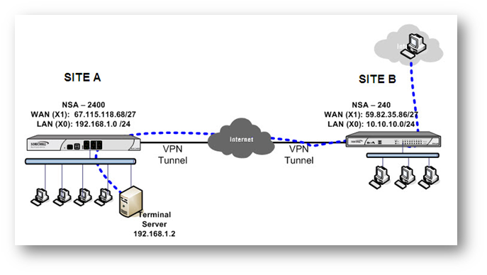
This article describes a scenario where a Site to Site VPN tunnel has been established between Site A and Site B; a Server behind Site A needs to be accessed by using the WAN IP address of Site B.
For the purpose of this article, we’ll be using the following IP addresses as examples to demonstrate the NAT policy creation. You can use these examples to create a NAT policy for your network, substituting your IP addresses for the examples shown here:
| Site A : TZ 670 X1 WAN IP: 67.115.118.68/27 X0 LAN Subnet: 192.168.1.0/24 Terminal Server on LAN: 192.168.1.2 | Site B : TZ 470 X1 WAN IP: 59.82.35.86/27 X0 LAN Subnet: 10.10.10.0/24 |
Procedure:
Configuration on Site B SonicWall (TZ 470)
This article assumes that a site to site VPN tunnel is already established between the two sites and traffic is flowing between them. The process of routing the traffic reaching the X1 interface of Site B SonicWall bound for the server at Site A through the VPN tunnel, involves the following:
- Creating an Address Object for the Terminal Server.
- Creating a rule from WAN to VPN.
- Creating a NAT Policy.
Creating an Address Object for the Terminal Server:
- Login to the GUI of SonicWall at Site B
- Navigate to Object|Match Objects | Addresses.
- Click on the Add button to create the following address object.

Creating a rule from WAN to VPN in the Site B SonicWall.
- Navigate to the Policy | Rules and Policies | Access Rules.
- Go to WAN | VPN page.
- Click on Add to create the following access rule.

Creating a NAT Policy in the Site B SonicWall
- Navigate to the Policy | Rules and Policies | Access Rules.
- Click on Add to create the following NAT Policy.
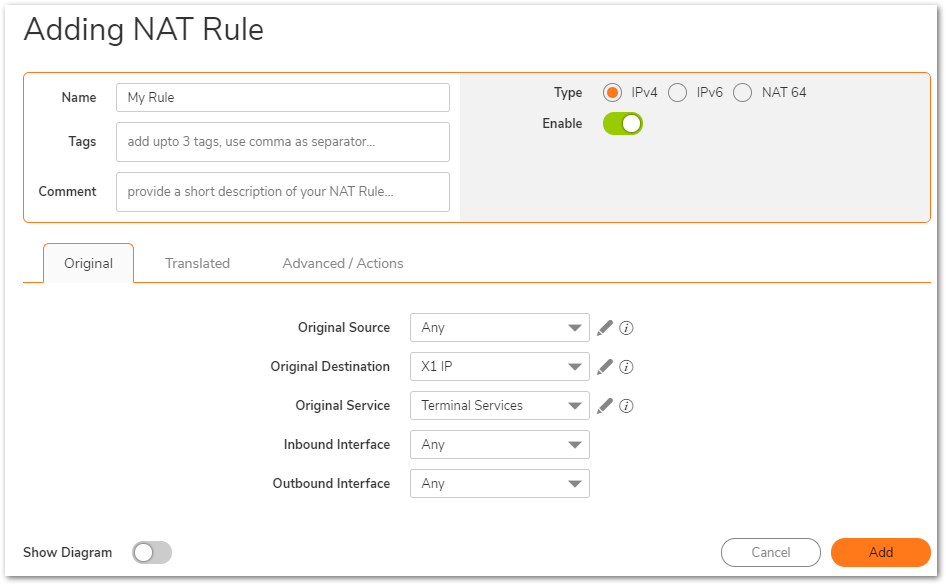

As the request is coming from the Internet and is not part of the VPN tunnel, the purpose of this NAT Policy is to translate the source IP address to that of the X0 subnet of the SonicWall so it can traverse the tunnel. The server at Site A sees a request from the LAN IP address of the SonicWall at Site B.
How to Test:
From the Internet have a host do a remote desktop connection to the ip address, in this case, 59.82.35.86
Troubleshooting:
- Make sure the Terminal Server address object has zone as VPN.
- Make sure the Terminal Server's default gateway is pointing to the SonicWall LAN IP address (Site A).
- Make sure there are no other conflicting NAT Policies or Access Rules at either end to block traffic.
- Make sure the Terminal Server has Terminal Services enabled and no personal firewall application is blocking it.
Resolution for SonicOS 6.5
This release includes significant user interface changes and many new features that are different from the SonicOS 6.2 and earlier firmware. The below resolution is for customers using SonicOS 6.5 firmware.
Feature/Application:
This article describes a scenario where a Site to Site VPN tunnel has been established between Site A and Site B; a Server behind Site A needs to be accessed by using the WAN IP address of Site B.
For the purpose of this article, we’ll be using the following IP addresses as examples to demonstrate the NAT policy creation. You can use these examples to create a NAT policy for your network, substituting your IP addresses for the examples shown here:
| Site A : NSA 2400 X1 WAN IP: 67.115.118.68/27 X0 LAN Subnet: 192.168.1.0/24 Terminal Server on LAN: 192.168.1.2 | Site B : NSA 240 X1 WAN IP: 59.82.35.86/27 X0 LAN Subnet: 10.10.10.0/24 |
Procedure:
Configuration on Site B SonicWall (NSA 240)
This article assumes that a site to site VPN tunnel is already established between the two sites and traffic is flowing between them. The process of routing the traffic reaching the X1 interface of Site B SonicWall bound for the server at Site A through the VPN tunnel, involves the following:
- Creating an Address Object for the Terminal Server.
- Creating a rule from WAN to VPN
- Creating a NAT Policy.
Creating an Address Object for the Terminal Server
- Login to the GUI of SonicWall at Site B
- Navigate to Manage | Objects | Address object.
- Click on the Add button to create the following address object.

Creating a rule from WAN to VPN in the Site B SonicWall.
- Navigate to the Manage | Rules | Access Rules.
- Go to WAN | VPN page.
- Click on Add to create the following access rule.

Creating a NAT Policy in the Site B SonicWall.
- Navigate to the Manage | Rules | NAT Policies page.
- Click on Add to create the following NAT Policy.

As the request is coming from the Internet and is not part of the VPN tunnel, the purpose of this NAT Policy is to translate the source IP address to that of the X0 subnet of the SonicWall so it can traverse the tunnel. The server at Site A sees a request from the LAN IP address of the SonicWall at Site B.
How to Test:
From the Internet have a host do a remote desktop connection to the ip address, in this case, 59.82.35.86
Troubleshooting:
- Make sure the Terminal Server address object has zone as VPN.
- Make sure the Terminal Server's default gateway is pointing to the SonicWall LAN IP address (Site A).
- Make sure there are no other conflicting NAT Policies or Access Rules at either end to block traffic.
- Make sure the Terminal Server has Terminal Services enabled and no personal firewall application is blocking it.
Resolution for SonicOS 6.2 and Below
The below resolution is for customers using SonicOS 6.2 and earlier firmware. For firewalls that are generation 6 and newer we suggest to upgrade to the latest general release of SonicOS 6.5 firmware.
Feature/Application:
This article describes a scenario where a Site to Site VPN tunnel has been established between Site A and Site B; a Server behind Site A needs to be accessed by using the WAN IP address of Site B.
For the purpose of this article, we’ll be using the following IP addresses as examples to demonstrate the NAT policy creation. You can use these examples to create a NAT policy for your network, substituting your IP addresses for the examples shown here:
| Site A : NSA 2400 X1 WAN IP: 67.115.118.68/27 X0 LAN Subnet: 192.168.1.0/24 Terminal Server on LAN: 192.168.1.2 | Site B : NSA 240 X1 WAN IP: 59.82.35.86/27 X0 LAN Subnet: 10.10.10.0/24 |
Procedure:
Configuration on Site B SonicWall (NSA 240)
This article assumes that a site to site VPN tunnel is already established between the two sites and traffic is flowing between them. The process of routing the traffic reaching the X1 interface of Site B SonicWall bound for the server at Site A through the VPN tunnel, involves the following:
- Creating an Address Object for the Terminal Server.
- Creating a rule from WAN to VPN
- Creating a NAT Policy.
Creating an Address Object for the Terminal Server
- Login to the GUI of SonicWall at Site B
- Navigate to Network | Address object.
- Click on the Add button to create the following address object.

Creating a rule from WAN to VPN in the Site B SonicWall.
- Navigate to the Firewall | Access Rules.
- Go to WAN | VPN page.
- Click on Add to create the following access rule.

Creating a NAT Policy in the Site B SonicWall.
- Navigate to the Network | NAT Policies page.
- Click on Add to create the following NAT Policy.

As the request is coming from the Internet and is not part of the VPN tunnel, the purpose of this NAT Policy is to translate the source IP address to that of the X0 subnet of the SonicWall so it can traverse the tunnel. The server at Site A sees a request from the LAN IP address of the SonicWall at Site B.
How to Test:
From the Internet have a host do a remote desktop connection to the ip address, in this case, 59.82.35.86
Troubleshooting:
- Make sure the Terminal Server address object has zone as VPN.
- Make sure the Terminal Server's default gateway is pointing to the SonicWall LAN IP address (Site A).
- Make sure there are no other conflicting NAT Policies or Access Rules at either end to block traffic.
- Make sure the Terminal Server has Terminal Services enabled and no personal firewall application is blocking it.